Everloft 1: Overview
With the lessons learned from our initial prototype, we are ready to move to the next phase. The goal for Everloft 1 is to prove that unstable flight with active stabilization is possible on a more realistic and optimized solar-powered UAV, rather than solely on a test platform.
This allows us to prove our optimization methods, measure accurate flight test data, and verify our simulations. Despite being an early prototype, Everloft 1 includes a custom-built battery pack and is designed to accommodate a larger battery pack and solar panels in the future, allowing for all-day and potentially all-night flights.
Primary Design Decisions
Before starting design optimization, we defined the most important design parameters and constraints. These decisions ensured that the goals set for Everloft 1 were achievable while keeping cost and prototyping time low.
Constraints- Wingspan - Limited to 3m. This ensures the aircraft remains easy to handle and transport while being sufficient to reach the goals set for Everloft 1.
- Launch and Landing - We selected a rail system for launch. This eliminates the mass and complexity of landing gear required for runway launching and achieves higher speeds and better repeatability than hand launching. Landing is performed in an elastic net to prevent damage.
- Battery - We selected Li-ion 21700 cells. This was the lowest-cost option due to the immediate availability of a sufficient number of cells.
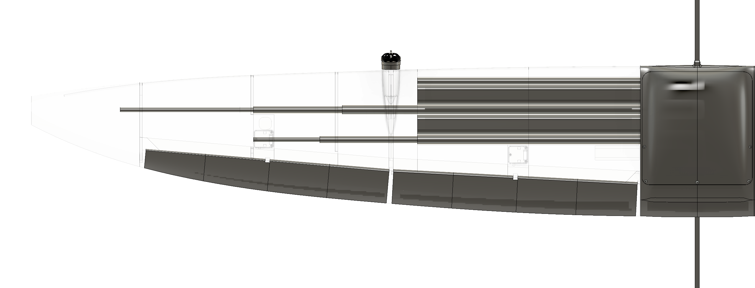
- Main structure - We selected straight composite tubes. This constrains the wing shape to no sweep and no dihedral but considerably simplifies and lightens the structure.
- Wing Geometry - We opted to 3D-print the wing geometry from Lightweight PLA, acting as a structural skin around the main structure. This allows for complex wing and airfoil shapes while keeping weight low.
- Stability - We decided to perform the first flights in a stable configuration, with a vertical stabilizer and increased inertia. This minimizes the risk of inaccurate controller gains from pre-tuning.
- Control Surfaces - We selected four control surfaces acting as elevons. This leads to smaller, stiffer control surfaces compared to a configuration with only two elevons.
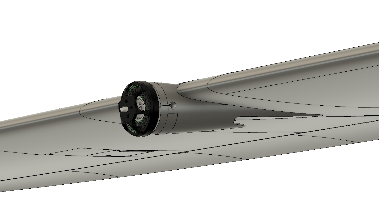
- Motors - We integrated two motors, one on each side. This allows testing active yaw stabilization using differential thrust, which is a requirement for the subsequent tailless design.
Design Optimization
Based on these design constraints and engineering decisions, we optimized the aircraft for maximum flight time over a simulated day-night cycle. We achieved this by writing a Multi-disciplinary Design Optimization (MDO) script in Python, called “Loftimizer,” which optimizes designs using an evolutionary algorithm. This method allows us to optimize all primary sizing variables of the UAV, such as wing geometry, battery mass, and solar panel area, while accounting for the interactions between them.
Of all modeled subsystems, aerodynamic performance is simulated with the highest fidelity. This part of the script generates complex wing geometries based on polynomial functions for the chord, sweep, twist, and dihedral along the span. The aerodynamic performance of the generated UAV is automatically simulated in XFLR5 to output the required power at the optimal speed and angle of attack.
The required power is used to calculate the maximum flight time, based on which the design is scored, alongside additional factors such as total mass.
For higher-fidelity optimization of subsystems, separate scripts are used:
- Airfoil - The airfoil geometry has a significant impact on aerodynamic efficiency. A script simulates the performance of every airfoil in a database of over 22,500 geometries using XFOIL. This data is used to output the best-performing airfoils for our operating conditions.
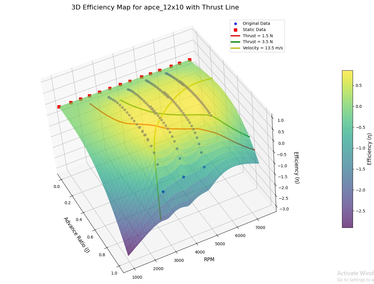
- Motor + Propeller - The efficiency of the motor-propeller combination is simulated using propeller data from the UIUC Propeller Data site and motor efficiency data from the Tyto Robotics motor database. Efficiency curves are constructed using this data, allowing us to estimate the total efficiency at the correct operating point and output the best-performing combinations.
- Main structure - Structural calculations are performed in a separate Python script using bending theory methods. This script sizes the main structure based on strength and stiffness constraints in the most critical load cases.
Final Design
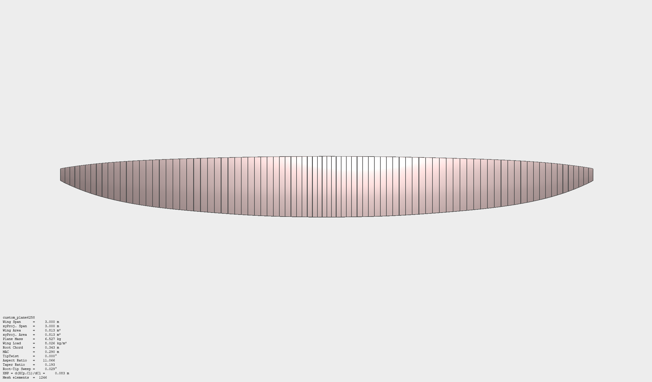
The output of the MDO script defined the following wing shape and parameters. For this, we iterated the optimization constraints based on preliminary component layouts in CAD. This ensured that the carbon spars and batteries fit within the wing while placing the C.G. in the correct position. Due to this, the sweep, twist and dihedral optimization features of the MDO script were disabled.
The parameters are sized for the future large-battery mission profile; therefore, the plane will initially operate at a reduced wing loading and weight.
- Battery Mass: 4.54kg
- Total Mass: 6.53kg
- Wingspan: 3m
- Wing Area: 0.81m2
- Aspect Ratio: 11
- Cruise Speed: 13.6 m/s
- Cruise Angle of Attack: 5.5deg
- Cruise Static Margin: -8
- Cruise Power Required: 60W
- Flight Time (battery only): 16h
- Flight Time (solar): 36h
- Airfoil: HQ 2.5/9.0
- Motor: T-Motor Antigravity M4006
- Propeller: Aeronaut CAM Carbon 12x10 Folding Prop
- Structure: 3 Carbon Tube Spars, increasing in diameter towards the wing root for structural efficiency
Manufacturing
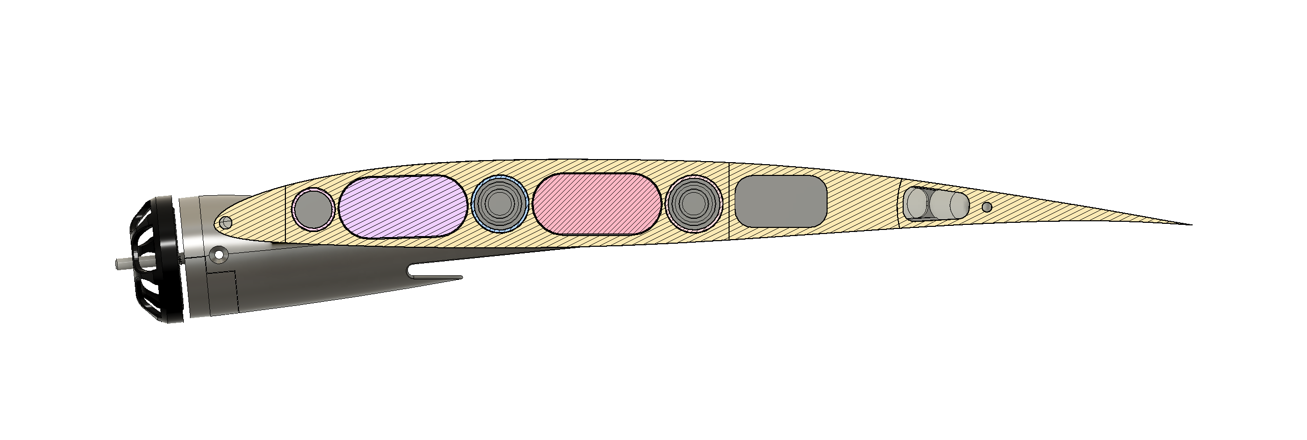
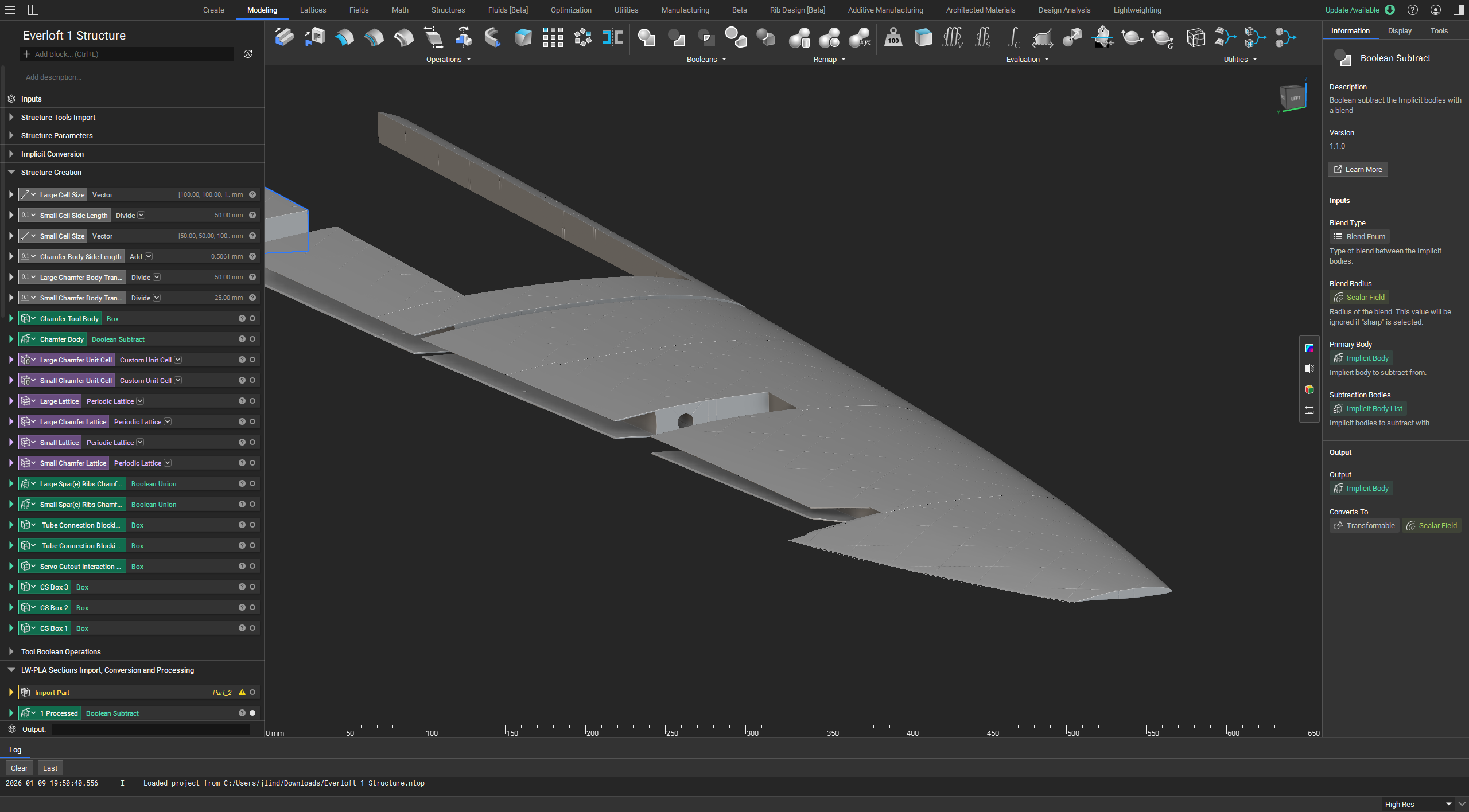
We performed the detailed CAD design in Fusion 360. This included modeling control surfaces, servo mounts, motor mounts, cable channels, and a central section housing the electronics. For most components, we performed multiple test prints and integrated the lessons learned directly into the design.
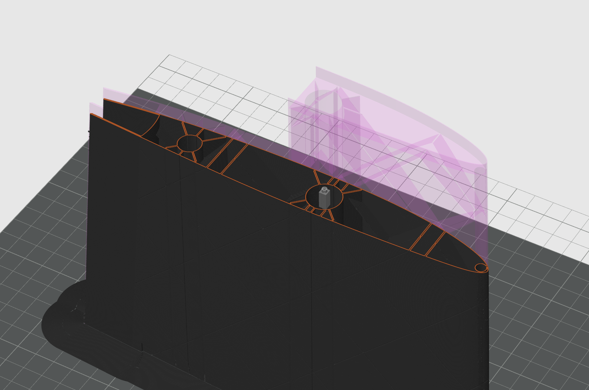
Foaming LW-PLA is best printed in a single continuous line per layer to eliminate retractions. To achieve this, the CAD model requires complex geometry, such as small "cuts" at rib locations and special handling of rib intersections. We found the Fusion 360 geometry kernel too slow and unreliable for generating these features, which prevented quick design iteration. Consequently, we switched to nTop for this, which uses implicit modeling to accelerate the process.
The required size and density of the rib structure were determined using test prints, allowing us to fine-tune the balance between weight and structural strength.
The building process for Everloft 1 is underway. Simultaneously, the launch rail is being assembled. More information will follow in a future update.